Recent Post
Showing posts with label Indicators. Show all posts

Tuesday, 14 January 2014

Maximum Minimum Voltage Indicator

This circuit indicates which of three voltages in the range from about about -4V to about +4V - at A, B and C - is the highest by lighting one of three indicator LEDs. Alternatively, it can be wired to indicate the lowest of three voltages or to indicate both the highest and lowest voltages. Op amps IC1a, IC1b & IC1c are wired as comparators, while the three indicator LEDs and their series 1kO current limiting resistors are strung across the op amp outputs to implement the appropriate logic functions.

Circuit diagram:
Maximum minimum voltage indicator circuit schematic

For example, LED A will light only when pin 8 of IC1c is low (ie, A greater B) and pin 7 of IC1b is high (ie, A greater C). Similarly, LED B will light only when pin 8 of IC1c is high (ie, B greater A) and pin 1 of IC1a is low (ie, B greater C). LED C works in similar fashion if the voltage at C is the highest. Note that if all the LEDs and their parallel 1N4148 diodes are reversed, the circuit will indicate the lowest of the three input voltages. And if each 1N4148 diode is replaced by a LED, the circuit will indicate both the highest and lowest inputs.
Author: Andrew Partridge - Copyright: Silicon Chip
Read more ...

Friday, 13 December 2013

Mains/Fuse Failure Indicator

The indicator shows when the mains is present at its output by a continuous glow of a neon bulb, La1, and when the fuse is blown by flashing of the neon bulb. When the fuse is intact, capacitor C2 acts as the series resistance for the neon bulb, so that this glows continuously. When the fuse has blow, the mains voltage across diode D1 is applied as a pulsating direct voltage to network R1-C1. Capacitor C1 charges slowly and when the voltage across it reaches 80–100 V, the neon bulb comes on. Capacitor C1 is then discharged slowly via diode D2 and the bulb.
Mains/Fuse Failure Indicator

When the voltage across it has dropped sufficiently, the bulb goes out, whereupon C1 slowly charges again. This process repeats itself, so that, provided the values of R1 and C1 are right, the bulb flashes visibly. The potential across capacitor C2 is a ramp with a peak value of 30 V (which is, of course, applied to the load). Note that the neon bulb used for this purpose must not be a type that has a built-in series resistor.
Read more ...

Monday, 9 December 2013

LED Bar Off Indicator

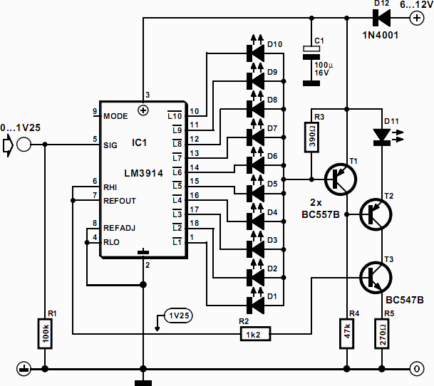
The simple indicator presented in this article may be combined, in principle, with any circuit that contains an LED bar display driven by a Type LM3914 IC. It ensures that an LED will light when all LEDs driven by the LM3914 are out. This prevents one drawing the erroneous conclusion that, since all the LEDs are out, the circuit is switched off. The circuit then continues to draw current, which, especially if it is battery powered, costs unnecessary money, apart from other considerations. The LED in the monitor draws a current of only 1 mA. When the LEDs forming the bar, D1–D10 are all out, there is no potential difference across R3, so that T1 is off and T2 is on.

Circuit diagram
LED Bar Off Indicator
LED Bar Off Indicator Circuit Diagram


This results in T3, in conjunction with R5 and the internal reference voltage of IC1, to form a current source that causes a constant current to flow through D11 so that the diode lights. When on of diodes D1–D10 lights, a potential difference ensues across R3, which causes T1 to come on. This results in T2 being switched off so that there is no collector current through T3. Consequently, there is no feedback at the emitter of T3, so that the current through R2 rises appreciably. The current through R2 determines the current through the LEDs in the bar. Therefore, when T3 is enabled, the current through R2, and thus the total current in the circuit, is reduced considerably.
Read more ...

Monday, 18 November 2013

Modem Off Indicator

The modem off indicator is intended especially for serious Internet surfers. It will be seen that the circuit of the indicator cannot be much simpler, or there might be nothing left. In spite of its simplicity, it may prove to be a cost-saving device, since it shows at a glance whether the telephone line is free again after the modem has been used. This obviates high telephone charges in case for some reason the modem continues to operate. The circuit depends on the fact that there is a potential of about 40 V on the telephone line when it is not busy. This voltage drops sharply when a telephone call is being made. If, therefore, the circuit is linked to telephone terminals a and b, the lighting of the green LED shows that the line is not busy in error.
Modem Off Indicator


The bridge rectifier ensures that the polarity of the line voltage is of no consequence. This has the additional benefit that polarity protection for the LED is not necessary. To make sure that the telephone line is not loaded unnecessarily, the LED is a high efficiency type. This type lights at a current as low as 2 mA, and this is, therefore the current arranged through it by resistor R1.

WARNING.
In spite of the liberal age we live in, it is highly probable that in many countries it is not allowed to connect the indicator across the telephone lines. Seek advice of your local telephone company that owns or operates the telephone network.
Read more ...

Saturday, 9 November 2013

Digital Main Voltage Indicator

Continuous monitoring of the mains voltage is required in many applications such as manual voltage stabilisers and motor pumps. An analogue voltmeter, though cheap, has many disadvantages as it has moving parts and is sensitive to vibrations. The solidstate voltmeter circuit described here indicates the mains voltage with a resolution that is comparable to that of a general-purpose analogue voltmeter. The status of the mains voltage is available in the form of an LED bar graph. Presets VR1 through VR16 are used to set the DC voltages corresponding to the 16 voltage levels over the 50-250V range as marked on LED1 through LED16, respectively, in the figure. The LED bar graph is multiplexed from the bottom to the top with the help of ICs CD4067B (16-channel multiplexer) and CD4029B (counter).

The counter clocked by NE555 timer-based astable multivibrator generates 4-bit binary address for multiplexer-demultiplexer pair of CD4067B and CD4514B. The voltage from the wipers of presets are multiplexed by CD4067B and the output from pin 1 of CD4067B is fed to the non-inverting input of comparator A2 (half of op-amp LM358) after being buffered by A1 (the other half of IC2). The unregulated voltage sensed from rectifier output is fed to the inverting input of comparator A2. The output of comparator A2 is low until the sensed voltage is greater than the reference input applied at the non-inverting pins of comparator A2 via buffer A1.
Digital Main Voltage Indicator

When the sensed voltage goes below the reference voltage, the output of comparator A2 goes high. The high output from comparator A2 inhibits the decoder (CD4514) that is used to decode the output of IC4029 and drive the LEDs. This ensures that the LEDs of the bar graph are ‘on’ up to the sensed voltage-level proportional to the mains voltage.The initial adjustment of each of the presets can be done by feeding a known AC voltage through an auto-transformer and then adjusting the corresponding preset to ensure that only those LEDs that are up to the applied voltage glow.

Note.
It is advisable to use additional transformer, rectifier, filter, and regulator arrangements for obtaining a regulated supply for the functioning of the circuit so that performance of the circuit is not affected even when the mains voltage falls as low as 50V or goes as high as 280V. During Lab testing regulated 12-volt supply for circuit operation was used.)
Read more ...